Direct answer: Continuous emissions monitoring works as a measurement chain. The system obtains a representative measurement from a stack or duct, preserves or measures the gas under controlled conditions, analyzes selected pollutants and supporting parameters, checks instrument response through quality-control functions, converts raw signals into required units, applies status and validity logic, and stores or transmits the resulting data. A CEMS is therefore not just a gas analyzer; it is an integrated sampling, analysis, calibration and data-handling system. What happens from the stack to the final emissions record?
The exact architecture depends on the pollutant, source and applicable rules, but most projects can be understood as six connected stages. A failure at any stage can produce unreliable data even when the analyzer itself is operating.
- Representative measurement: A probe or in-situ instrument is installed at a location selected to represent the gas stream and allow safe maintenance.
- Sample transport or optical measurement: An extractive system moves gas to a cabinet; an in-situ system measures across or within the duct.
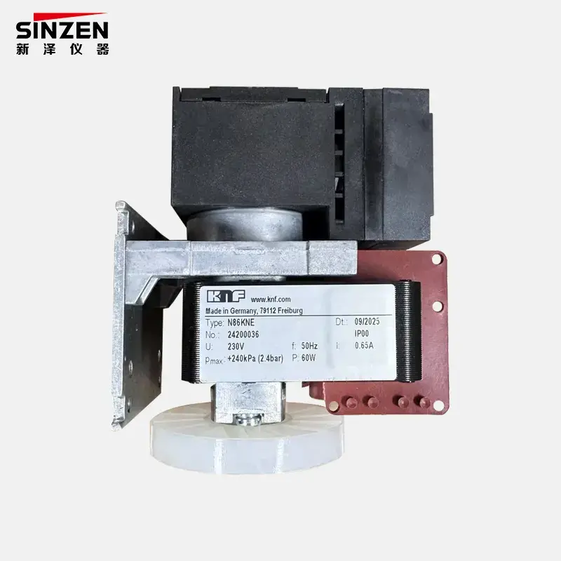
- Sample conditioning: Filtration, heating, cooling, drainage or pressure and flow control prepare the gas without losing or altering the target component.
- Analysis: The selected analyzer principle converts the target gas interaction into a concentration signal.
- Quality control: Zero, span, drift, alarm and maintenance states help determine whether data are valid.
- Data handling: Software calculates, averages, flags, stores and communicates values according to project requirements.
Buyers planning a complete system should review the gas analysis system category rather than evaluating the analyzer channel in isolation.
How do extractive and in-situ CEMS architectures differ?
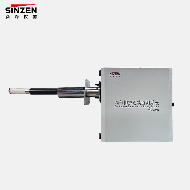
An extractive system takes gas from the duct and transports it to one or more analyzers. This allows a centralized cabinet and flexible analyzer combinations, but it makes probe design, line temperature, filtration, cooling and drainage critical. An in-situ system measures directly in or across the stack, reducing the transported sample path but increasing the importance of installation geometry, optical path, purge or protection functions and access at the measurement point.
Architecture comparison for project planning | Factor | Extractive approach | In-situ approach |
| Measurement location | Gas is transported to an analyzer cabinet | Measurement occurs in or across the duct |
| Critical design area | Sample integrity through probe, line and conditioning | Optical or sensor installation, path conditions and protection |
| Maintenance location | Much of the equipment can be serviced at cabinet level | More work may occur at the stack installation point |
| Typical risk | Condensation, adsorption, blockage, leaks or transport delay | Dust loading, alignment, purge failure or unsuitable path |
| Selection basis | Target gases, matrix, dust, moisture, temperature, response needs, access and applicable performance requirements |
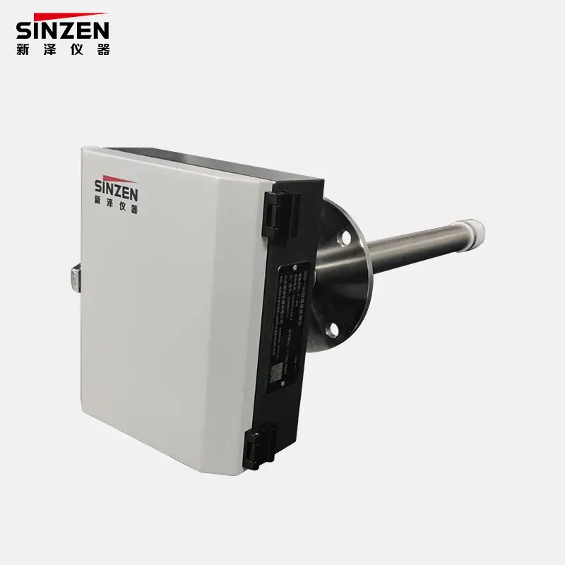
SINZEN lists an in-situ CEMS within its system portfolio. Whether an in-situ or extractive route fits a project must be confirmed against the actual source conditions and measurement objectives.
Why is sample conditioning often the decisive part of an extractive CEMS?
Stack gas can contain dust, water vapor, aerosols and corrosive components at elevated temperature. The conditioning system must protect the analyzer while keeping the target gas representative. Cooling a wet sample without understanding solubility or reaction risk can remove part of the component being measured. Keeping the path heated may preserve the sample but increases temperature-control and maintenance requirements.
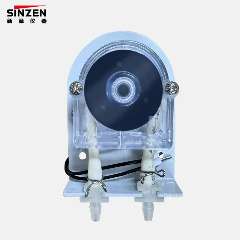
A heated sampling tube is therefore not a universal add-on. Its temperature range, length, materials, insulation, power and control must match the probe, sample flow and gas chemistry. The same applies to filters, condensers, pumps, drains and tubing.
How does the analyzer turn gas into a measurement?
Gas analyzers use different physical or chemical principles. The correct choice depends on the target component, expected range, moisture, interfering gases, response time, maintenance capability and whether the measurement remains wet or is converted to a dry basis. A multi-component system may combine more than one principle.
The buyer should ask the supplier to explain why the proposed method fits the full gas matrix. A statement such as “infrared analyzer” or “laser analyzer” is not enough. The quotation should clarify the measured components, ranges, basis, sample state, interference treatment and calibration approach. This is especially important when one cabinet serves changing fuel or process conditions.
How are calibration and data validity handled?
Continuous output is not automatically valid output. A CEMS needs defined checks that expose drift, loss of sample flow, cabinet temperature problems, maintenance periods and other abnormal states. Zero and span functions help evaluate analyzer response; the exact frequency, acceptance criteria and test method must follow the applicable project requirements.
The data system should retain both measurements and status information. It may calculate normalized values, oxygen-corrected values, averages or mass emission rates when the required supporting measurements and formulas are specified. Buyers should define which values are raw, corrected, validated or substituted and who has authority to change configuration settings.
Data and quality-control questions for an RFQ | Topic | Buyer question | Why it matters |
| Calibration path | How does zero/span gas reach the analyzer or complete sample path? | A partial-path check may not reveal probe or line problems |
| Status handling | Which faults invalidate, flag or merely alarm the data? | Operators must distinguish a process event from an instrument event |
| Calculation basis | Which temperature, pressure, moisture, oxygen and flow inputs are used? | Incorrect bases create non-comparable results |
| Data interface | Which analog, digital and network protocols are required? | Late integration changes delay commissioning |
| Audit trail | Are calibration, maintenance and configuration changes recorded? | Historical values need operational context |
Where do CEMS projects commonly fail after purchase?
Six experience-based problems are more common than analyzer specification errors:
- Unrepresentative sampling location: convenient access is chosen without reviewing flow profile or source geometry.
- Unspecified wet or dry basis: supplier and buyer compare values that have different moisture bases.
- Undersized conditioning capacity: high dust, condensate or changing load overwhelms filters, cooler or drain components.
- Analyzer range selected from normal operation only: start-up or upset values exceed the configured range.
- No interface ownership: the CEMS vendor, PLC contractor and environmental software provider each assume another party will map the data.
- Maintenance access omitted: the system can measure, but filters, cylinders or stack instruments cannot be serviced safely and quickly.
Scenario: Continuous monitoring for a waste-incineration line
Business Background: An EPC contractor is sourcing a continuous monitoring package for a new waste-incineration project.
Problem: The initial gas list is clear, but suppliers propose different sample temperatures, conditioning designs, calibration scope and data interfaces.
Cause: The tender defines analyzer outputs but not moisture basis, dust loading, acid-gas preservation, calibration path or responsibility for the plant reporting interface.
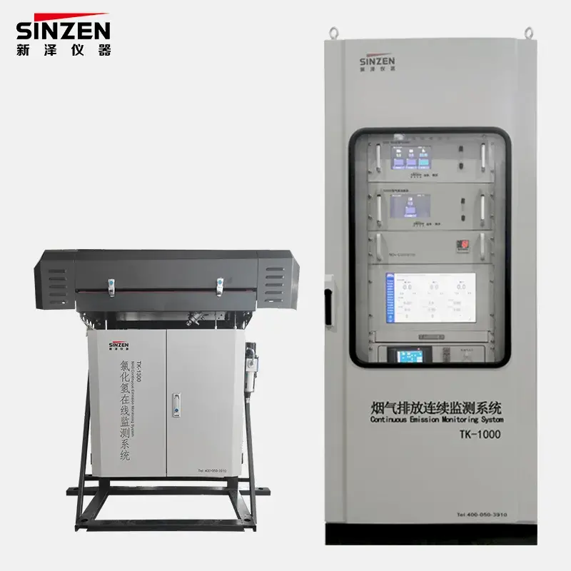
Solution: The EPC team issues a measurement-basis table, expected operating envelopes, utility and interface list, required quality-control sequence and maintenance-access plan. It then compares complete measurement chains rather than analyzer prices. SINZEN’s CEMS for solid waste incineration can be reviewed as a project-specific application option, with final configuration based on the tender requirements.
How should buyers define a CEMS quotation request?
A technically comparable RFQ should include the source and process, fuel or feed variation, target components, normal and maximum ranges, wet/dry basis, stack temperature and pressure, moisture and dust, sampling location, required response, applicable performance and reporting requirements, flow and particulate scope, utilities, cabinet environment, communication protocol, calibration approach, spares, training and commissioning responsibilities.
Application-specific systems can require different measurement and sample-handling priorities. For example, a natural gas boiler CEMS should not be copied unchanged into a high-dust or acid-gas application simply because both projects use the term CEMS.
Frequently asked questions
Does continuous mean the analyzer reports every second?
Not necessarily. Measurement cycle, recording interval and reporting average are separate requirements and must be defined by the applicable project rules.
Is a gas analyzer alone a CEMS?
No. A complete CEMS includes the equipment and data functions needed to obtain, validate, calculate and report the required emission measurement.
Why does an extractive CEMS use a heated line?
Heating can help prevent unwanted condensation and preserve the sample, but the required temperature and materials depend on the gas matrix and conditioning design.
Can one CEMS configuration monitor every industrial stack?
No. Pollutants, ranges, dust, moisture, temperature, access and regulatory requirements vary substantially by source.
What is the difference between concentration and emission rate?
Concentration describes pollutant quantity within a gas volume. Emission rate combines concentration with flow and the required correction basis to express pollutant mass over time.
Why are calibration status and maintenance records stored with the data?
They help users determine whether a change came from the process or from the measurement system and whether data meet the project’s validity rules.
What information is essential before CEMS pricing?
At minimum, provide gases, ranges, sample basis, source conditions, measurement location, applicable requirements, data interface, utilities and project responsibility boundaries.
Request a CEMS configuration review
Provide the industrial process, fuel or feed, target components and ranges, wet/dry basis, stack temperature, pressure, moisture, dust, flow conditions, installation point, applicable standard, required outputs, utilities and project schedule. SINZEN can review the measurement architecture, sample conditioning, analyzer channels and interface scope for a comparable quotation. Use the SINZEN contact page to submit the project details.