An OEM gas analyzer module should not be selected by gas name and measuring range alone. A system integrator must freeze the target gas, normal and upset concentrations, background-gas composition, moisture, dust, sample temperature and pressure, measurement principle, power supply, output interface, communication method, dimensions, calibration method and host-system responsibility. These inputs determine whether the module can measure the intended gas and whether it can function inside the finished instrument. Module compatibility is therefore not only measurement compatibility; it combines sample, mechanical, electrical, communication, software and calibration compatibility. A useful RFQ should define every interface, identify what sample conditioning already exists and require the supplier to distinguish confirmed specifications from assumptions, alternatives and information that still needs buyer review.
Start With the Gas Measurement Duty, Not the Module Size
Compact dimensions are important in an embedded instrument, but they do not define the measurement duty. The integrator should first explain why the gas is being measured and how the result will be used. Possible duties include process monitoring, an emissions subsystem, safety monitoring, an OEM analyzer, a laboratory instrument or a gas-analysis cabinet.
The same target gas can create different module requirements in each application. A process-control channel may prioritize response and stable output around a control point. A safety-monitoring channel may require specific alarm behavior and fault handling within a broader system architecture. A laboratory instrument may emphasize flexible ranges, calibration access or data recording. An emissions subsystem may need the result to follow a defined reporting basis and quality procedure.
The buyer should therefore define the measurement decision before asking for a module model. The SINZEN OEM gas module range provides a relevant product-discovery path, but the final choice must follow the intended duty and integration conditions.
Which Gas and Range Inputs Must Be Frozen First?
| Buyer Input | Why It Matters | Supplier Must Confirm | Risk if Missing |
| Target gas | Defines the required measurement channel | Supported component and principle | Wrong module family |
| Normal concentration | Sets the useful operating window | Configured span and resolution basis | Poor usable resolution |
| Minimum or control point | Shows where decisions are made | Performance at the relevant point | Weak control discrimination |
| Upset maximum | Defines over-range exposure | Maximum supported condition and recovery | Saturation or delayed recovery |
| Background gas | Affects principle and interference review | Gas-matrix compatibility | Unrecognized measurement bias |
| Moisture and dust | Determine sample-conditioning needs | Allowable inlet condition | Instability or contamination |
| Sample pressure | Affects the measuring condition and flow | Allowable inlet range and control method | Reading error or mechanical mismatch |
| Sample temperature | Defines transport and conditioning duty | Allowed module-inlet condition | Condensation or damage |
“Range” should not mean only the largest number the module can display. The normal band determines whether the output is useful around the operating point, while the upset maximum determines whether the module will saturate or require protection. The quotation should state the configured range, engineering unit, output mapping and any assumptions about sample conditioning.
Why Does the Background Gas Matter to an OEM Module?
The target component exists within a gas matrix. Major balance gases, interfering components, corrosive species, hydrocarbons, moisture and changing process composition may influence measurement-principle selection, optical or sensing behavior, wetted materials and pretreatment. A request that says only “CO module” leaves this context undefined.
The integrator should provide the expected composition, including normal values and credible peaks for relevant components. If the full composition is unknown, the RFQ should identify that uncertainty instead of presenting a simplified mixture as complete. The supplier should return the proposed measurement principle, known interference boundaries relevant to the stated matrix, required sample assumptions and pretreatment requirements.
This review also prevents a category error. A module capable of measuring a target gas in clean calibration mixtures may not be ready to accept a hot, wet, dusty or chemically aggressive industrial sample. Measurement capability and raw-process-gas compatibility are separate decisions.
The Module and Sample System Must Be Designed Together
Many OEM modules expect a defined inlet condition: controlled flow, stable pressure, an acceptable temperature range and a sample free from damaging particles or condensate. If the process gas contains high moisture, dust, aerosols, condensate or excessive heat, the integrator must design an appropriate path between the process and the module.
The functional chain is:
Process Gas → Pretreatment → Flow and Pressure Control → Gas Analyzer Module
Pretreatment may involve filtration, cooling, drying, heated transport, condensate separation, pressure regulation or other project-specific stages. The correct arrangement depends on the target gas and measurement principle. Conditioning must protect the module without removing or changing the component being measured.
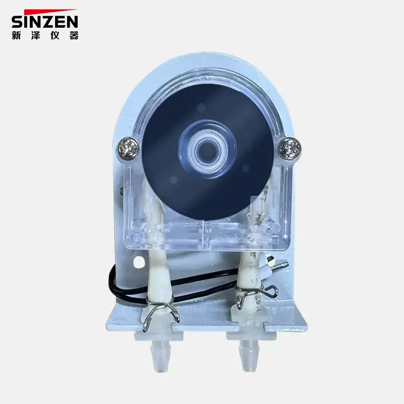
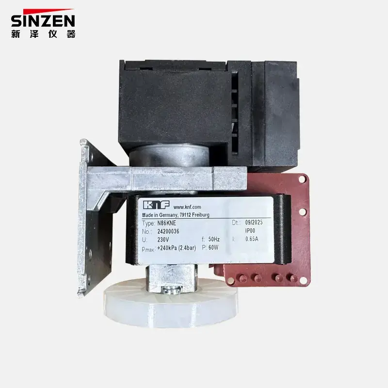
The RFQ should state what sample system the OEM already provides and what the module supplier is expected to supply or validate. It should also define inlet connection, allowable flow and pressure, exhaust routing and whether the module draws the sample or depends on an external pump. Without this boundary, two technically different quotations may appear comparable.
Electrical Compatibility Goes Beyond Supply Voltage
Matching the nominal supply voltage is necessary but not sufficient. Integrators should define the available voltage range, stability, current capacity, startup behavior, grounding strategy, electrical isolation needs and connector arrangement. The module supplier should state actual power requirements and interface conditions for the offered model.
The output can be analog, digital or a combination, but the article or RFQ should not assume a particular current signal, voltage signal, serial link or protocol unless the product documentation confirms it. The buyer should identify the required interface, and the supplier should return the exact supported output, pin definition, protocol and data format.
Connector compatibility also requires more than matching shell shape. Pin allocation, keying, mating component, cable direction and service access must be checked. Where the OEM adds an adapter board or signal converter, ownership of that interface and its verification should be explicitly assigned.
How Should the Host System Interpret the Module Output?
A module output is not yet a finished measurement channel. The host controller, PLC, industrial PC or embedded board must convert that output into an engineering value and apply the correct operating logic. The integration chain is:
Raw Output → Scaling → Engineering Unit → Alarm or Control Logic → Display and Storage
The OEM should confirm the engineering unit, configured range, analog scaling or digital register mapping, update requirement and expected response to module faults. It should also define what the host does during warm-up, calibration, over-range, invalid data and communication loss.
A module can measure correctly while the finished instrument displays the wrong value because the host uses the wrong span or unit. The sample-approval plan should therefore test both the module output and the value interpreted by the host. Data mapping belongs in the controlled integration specification, not only in software notes held by one developer.
Calibration Responsibility Must Be Defined Before Integration
The buyer should ask whether the offered module is calibrated as a standalone component, what gas and conditions are used, what records are supplied and whether any configuration is fixed for the order. That still does not automatically establish the performance of the completed OEM instrument.
Integration can introduce sample-path losses, flow differences, electrical scaling errors, software mapping problems or thermal effects. The OEM may therefore need zero and span verification, host-scaling verification, system-level calibration and a final factory acceptance test. The required work depends on the module, finished product and application; it should not be assumed that either the module supplier or integrator owns every step.
A clear responsibility matrix should identify who supplies calibration gas, who performs module-level testing, who verifies the assembled instrument and who issues the final record. It should also define what happens after a module replacement, firmware change, range change or repair.
What Should a Module Sample-Approval Test Verify?
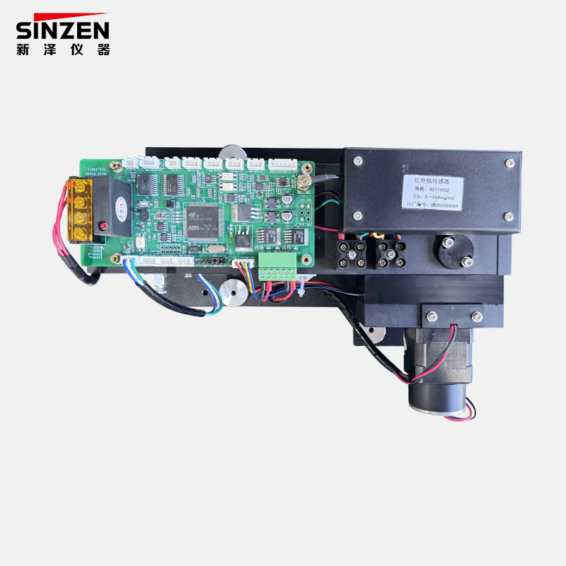
Powering on the sample is only the beginning. A structured approval process should cover five areas:
- Physical fit: dimensions, mounting points, orientation, cooling space, connector access and sample-port access.
- Electrical fit: supply behavior, grounding, power consumption, outputs, pin definition and communication interface.
- Measurement: zero response, span response, selected gas and range, repeatability under the agreed test conditions and recovery from the stated operating range.
- Host integration: scaling, unit, update behavior, displayed value, alarm or control mapping, calibration state, fault indication and communication-loss response.
- Representative conditions: sample pressure, flow, temperature, moisture or relevant gas-matrix conditions defined for approval.
The approval path should be Sample → Verification → Deviation Review → Approval → Bulk Order. The sample record should capture the module model and revision, host hardware and software version, test gases, conditions, results and approved deviations. This prevents a successful bench trial from being applied to a changed production configuration without review.
What Can Go Wrong When Buyers Order Only by Gas and Range?
The gas is correct but the matrix is wrong
The module detects the target component, but the background gases or interferents were never reviewed for the process.
The range is correct but the sample condition is wrong
The span covers the expected concentration, yet moisture, dust, pressure or condensate makes the bare-module arrangement unsuitable.
The module works but the host cannot read it
The output type, protocol, pinout or electrical levels do not match the OEM controller.
The output works but the scaling is wrong
The host maps the signal to the wrong engineering range or unit, producing an incorrect displayed value.
The bench sample works but the final instrument fails acceptance
Module-level calibration and finished-instrument verification were treated as the same responsibility, leaving sample-path and host-integration errors undetected.
How Should Buyers Evaluate SINZEN’s OEM Gas Module Range?
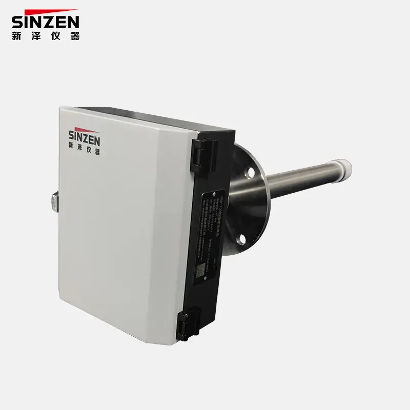
SINZEN’s OEM Gas Module category includes different product routes rather than one universal module. The SINZEN NDIR Gas Sensor Module provides a specific product-detail entry for integrators evaluating an NDIR-based option. Its presence confirms a real product family, but it does not establish that NDIR is the correct principle for every target gas or gas matrix.
The quotation must still identify the exact product and model, target component, range, measurement principle, acceptable sample condition, power, output, communication, dimensions, calibration status and supplied documents. Where another module family is more appropriate, the supplier should state the alternative and explain which buyer input changes the selection.
System integrators should also separate the module supply from any conditioning, pump, flow-control, interface-board, harness, housing or software scope. A single commercial line such as “OEM gas module” is not detailed enough for sample approval or repeat production.
What Should an OEM Gas Analyzer Module RFQ Include?
- Target gas or gases.
- Measurement purpose and final OEM instrument.
- Normal, minimum, maximum and upset concentrations.
- Engineering unit and required reporting basis.
- Background-gas composition and likely interferents.
- Sample temperature, pressure, moisture and dust.
- Required sample flow and exhaust conditions.
- Available pretreatment and responsibility boundary.
- Required measurement principle, if project-mandated.
- Power-supply range and electrical constraints.
- Required analog or digital output and communication interface.
- Host controller, PLC, IPC or embedded-system information.
- Available mechanical envelope, mounting and orientation.
- Connector, mating cable and pin-definition requirements.
- Response and update requirements.
- Scaling, unit, fault and alarm-state mapping.
- Module and system-level calibration responsibilities.
- Sample-approval test, quantity and bulk-order plan.
- Documentation, traceability and mandatory project requirements.
- Destination, packing and requested schedule.
Send this OEM interface specification through the SINZEN gas module inquiry form. Require the supplier to return each field as Confirmed, Deviation, Alternative or Buyer Input Required. That response creates a reviewable path from module selection to sample approval and repeat production.