A Furnace Gas Analysis System should be selected from the complete measurement task, not from the analyzer cabinet alone. Before comparing suppliers, buyers should confirm the measurement purpose, target gas components, expected concentration ranges, sampling point, process temperature and pressure, dust and moisture conditions, corrosive or condensable species, required response time, installation environment, utilities, signal interfaces, calibration expectations and RFQ documentation. These variables determine whether the project needs an extractive system, an in-situ approach, a heated or conditioned sample path, special sample-contact materials, or another configuration. The practical selection question is therefore: can the proposed system preserve a representative sample and produce usable data under the actual furnace conditions?
Start With the Measurement Decision the Plant Needs to Make
The first project condition is not the furnace temperature. It is the reason the plant needs the measurement. Furnace gas analysis can support different decisions, and each decision changes what must be measured and how quickly the result must be available.
A combustion-control application may focus on oxygen, carbon monoxide, carbon dioxide or another process indicator. A reducing or protective-atmosphere furnace may require composition control for a different set of gases. A metallurgical process may use gas composition to understand reaction conditions. An environmental or carbon-accounting project may require a different measurement basis, reference condition and documentation package.
These are not interchangeable specifications. If the buyer writes only “furnace gas analyzer,” the supplier has to guess which process decision the data must support. That can lead to a technically functional analyzer being paired with the wrong sample path, component list or response requirement.
The RFQ should therefore state the control objective in one or two sentences. A useful format is: “Measure these components at this point so the plant can make this operating or reporting decision.” That statement becomes the anchor for the rest of the system design.
For broader product discovery, SINZEN groups related solutions under its Industrial Process Gas Analysis System category. The category helps define the solution family, while the final system still has to be matched to the furnace process.
Which Gas Components and Concentration Ranges Actually Matter?
The next selection step is to freeze the component list and expected concentration range for each gas. A furnace can contain major components at percent level while another target species may exist at much lower concentration. The measurement principle, sample preparation and calibration plan may differ depending on that range.
Buyers should provide:
- the gas components that must be measured;
- normal concentration for each component;
- minimum and maximum expected concentration;
- start-up, shutdown or abnormal conditions if they materially change the range;
- whether the result is needed on a wet or dry basis;
- any known interferents that could overlap with the target measurement.
This avoids a common mismatch: a supplier selects an analyzer around the normal operating concentration, while the plant expects the same system to remain useful during a much wider upset range. Conversely, specifying an unnecessarily wide range can reduce the usefulness of the measurement for normal process control.
The component list also affects system architecture. If multiple gases must be measured simultaneously, the buyer should ask the supplier to show how the proposed analyzers, sample path and data outputs cover the complete list. If one component requires a different measurement principle or sample condition, that difference should be declared rather than hidden inside a generic “multi-gas system” description.
Sampling Point Conditions Can Change the Entire System Architecture
For extractive furnace gas analysis, the sampling point is part of the measurement system. The gas temperature, pressure, velocity, dust loading, moisture and chemical composition at that location determine what happens before the gas reaches the analyzer.
A representative RFQ should describe the sample point with process data rather than only a drawing location. Important inputs include:
- normal and maximum process temperature;
- positive or negative pressure at the sampling point;
- dust or particulate condition;
- moisture and condensation risk;
- presence of tar, oil mist, acid gases or other condensable/corrosive material;
- distance from the sampling point to the analyzer cabinet;
- available access for probe maintenance and filter cleaning.
High-temperature or high-dust process gas may require a robust extraction probe, filtration and cleaning strategy. Wet or condensable gas may require the sample path to be temperature-controlled or deliberately cooled and dried, depending on the target species and analyzer principle. The key is not to choose “heated” or “cooled” as a preference; the sample path has to preserve the gases that the project intends to measure.
This creates a complete engineering chain: process condition → sample behavior → conditioning requirement → analyzer inlet condition → measurement reliability. If the sample changes before it reaches the analyzer, a high-quality analyzer cannot recover the original composition.
Extractive or In-Situ Measurement Should Follow the Process, Not a Default Preference
Some furnace applications are better served by extractive systems; others may benefit from in-situ measurement. The decision depends on the gas component, process conditions, access, required response time, maintenance strategy and the available measurement technology.
An extractive system physically removes a sample from the process, transports it through a sample line, conditions it where necessary and sends it to the analyzer. This architecture gives flexibility to combine several analyzers in one cabinet and can isolate sensitive instruments from the furnace environment. It also creates additional responsibilities: probe condition, line temperature, filtration, moisture management, pumps and flow control all become part of the measurement chain.
An in-situ analyzer measures across or within the process without transporting a conventional sample to a remote cabinet. That can reduce sample-conditioning delay and some maintenance points, but it introduces its own installation, optical-path, access and process-condition constraints.
The selection should therefore be made component by component and application by application. The buyer should ask the supplier to explain why the proposed measurement architecture fits the stated furnace conditions and what operating boundary would cause that choice to change.
Sample Conditioning Must Protect Both Sample Integrity and the Analyzer
For an extractive Furnace Gas Analysis System, sample conditioning is not an accessory. It is the interface between the process and the analyzer.
The system may need some combination of probe filtration, heated transport, secondary filtration, gas cooling, condensate management, pressure regulation, flow control or protective functions. The correct combination depends on the sample rather than on a standard cabinet template.
The buyer should require the supplier to describe what each conditioning stage is intended to do. For example, filtration should address the expected particulate condition without removing the gas species of interest. A heated line should maintain the sample at the required condition through transport, not simply add heat. A cooler or moisture-removal stage should be evaluated against the target gases so that conditioning does not bias the measurement.
A useful system drawing should show the complete path:
Sampling point → probe → primary filtration → sample transport → conditioning → flow/pressure control → analyzer → exhaust or return.
That drawing is valuable because it makes hidden assumptions visible. If two suppliers propose different sample-conditioning chains, the buyer can evaluate whether they are solving the same process problem rather than comparing cabinet prices alone.
Response Time Depends on More Than the Analyzer Specification
Plants often ask how quickly the system will respond to a furnace change. The answer depends on the full measurement chain.
Analyzer response is only one part. Sample-line length, internal volume, extraction flow, conditioning equipment, filters and any gas-treatment stages can add transport and processing delay. An in-situ measurement may behave differently from a long extractive line even when both analyzers have fast internal response.
The RFQ should state the process decision that depends on response time. If the measurement is used for fast combustion adjustment or safety-related process awareness, the acceptable delay may be different from a trend-monitoring application.
Ask the supplier to distinguish between:
- analyzer response time;
- sample transport time;
- total system response or update time at the control system;
- conditions under which that response changes.
This prevents an analyzer-level specification from being mistaken for the response of the installed system.
Installation Conditions Determine Whether the System Can Operate as Quoted
A technically suitable analyzer still needs a suitable installation environment. Before supplier comparison, buyers should describe where the probe, sample line, cabinet and utilities will be located.
Relevant project inputs include ambient temperature, indoor or outdoor installation, enclosure expectations, distance to the process, available power, instrument air or purge gas where applicable, ventilation, drainage, calibration-gas arrangement and maintenance access. If the area has a hazardous classification or another site-specific safety requirement, that requirement must be stated explicitly.
The data interface also belongs in this section. The buyer should identify whether the control system expects analog outputs, digital communications, dry contacts, alarms, local display, remote status or another interface. Do not assume that a generic analyzer output matches the plant DCS or PLC architecture.
A site interface list is useful evidence because it turns installation from a late-stage engineering task into an RFQ input. Suppliers can then declare what is included, what is optional and what the buyer must provide.
What Evidence Should Buyers Require Before Shortlisting a Supplier?
Supplier evidence should prove the proposed measurement chain, not just the existence of a gas analyzer. A useful evaluation package may include a process/application questionnaire, component-range table, system flow diagram, sample-conditioning description, analyzer datasheets, interface list and proposed verification or calibration approach.
| Evidence | What the Buyer Should Check | Decision It Supports |
| System flow diagram | Probe, transport, conditioning, analyzer path, exhaust and key utilities | Confirms that the supplier has addressed the real sample condition |
| Component/range schedule | Each target gas, proposed range, measurement principle and stated limitations | Checks whether all required process measurements are covered |
| Sample-conditioning description | Filtration, heating/cooling, moisture handling, pressure and flow control | Shows how sample integrity and analyzer protection are managed |
| Installation/interface list | Power, gas utilities, signals, communications and buyer-supplied items | Prevents missing scope at installation |
| Verification/calibration plan | How zero/span checks, calibration gases, records or acceptance checks are handled | Defines how the buyer can verify measurement performance after installation |
| Deviation list | Any difference from the RFQ, process assumptions or excluded items | Makes supplier quotations technically comparable |
Evidence has value only when it is tied to the proposed configuration. A generic analyzer brochure does not prove that the probe and conditioning system will work with the stated furnace temperature, dust or moisture conditions.
How Should Buyers Review SINZEN’s Industrial Furnace Gas Analysis System?
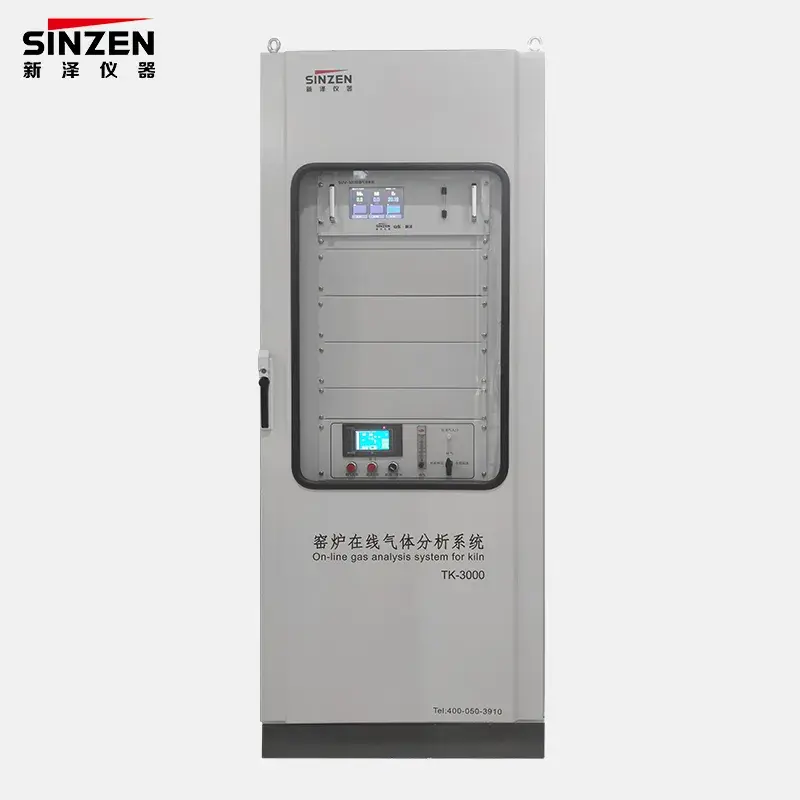
SINZEN’s Industrial Furnace Gas Analysis System page can be used as the target product-family reference for this selection process. The current client product record confirms that the solution belongs to the Industrial Process Gas Analysis System category and is supplied for B2B project applications with specification confirmation and customization support.
That product reference should be treated as the starting point for a project discussion, not as proof of every furnace duty. The product page alone cannot determine the buyer’s target gases, ranges, probe material, sample-conditioning design, response time, hazardous-area requirement, communications or acceptance method.
The final selection still depends on the project conditions described above. For a meaningful comparison, the supplier should return a configuration that is explicitly linked to the buyer’s furnace data and measurement objective.
When Should the Selection Logic Change?
This selection path applies to an industrial furnace gas measurement project where the buyer is choosing an online or integrated analysis system. It should be reconsidered when the primary need is different.
If the project is a laboratory batch-analysis task, a laboratory gas chromatograph or another analytical method may be more appropriate than a continuous process system. If the main need is a dedicated personnel or area safety alarm, the project may require a gas alarm device rather than a process gas analysis architecture. If a single gas can be measured reliably in situ and rapid response is the dominant requirement, an in-situ analyzer may deserve separate evaluation.
The conclusion also changes when a regulation or customer specification prescribes a particular measurement method, performance specification or reporting basis. In that case the applicable requirement should control the analyzer selection rather than a general process preference.
Build the Final Furnace Gas Analysis System RFQ Around the Process
A complete RFQ should include:
- furnace type and process description;
- measurement purpose and control/reporting decision;
- target gas components;
- normal, minimum and maximum concentration ranges;
- sampling-point location;
- normal and maximum gas temperature;
- process pressure or draft condition;
- dust, moisture, condensable and corrosive-gas conditions;
- required wet/dry measurement basis;
- acceptable response time or control-loop need;
- extractive or in-situ preference if already constrained by the project;
- distance from sample point to analyzer location;
- ambient and installation environment;
- available utilities;
- DCS/PLC signal and communications requirements;
- calibration or verification expectations;
- document and drawing requirements;
- quantity and project schedule context;
- required spare, maintenance or consumable scope;
- supplier deviations, assumptions and exclusions.
Ask suppliers to return each critical item as Confirmed / Proposed Configuration / Deviation / Optional / Buyer Input Required. This turns the inquiry into a project-specific technical comparison rather than a generic request for a gas analyzer cabinet.
Once those inputs are fixed, buyers can submit the project through SINZEN’s contact and RFQ page with the measurement objective, furnace conditions and interface requirements already defined.