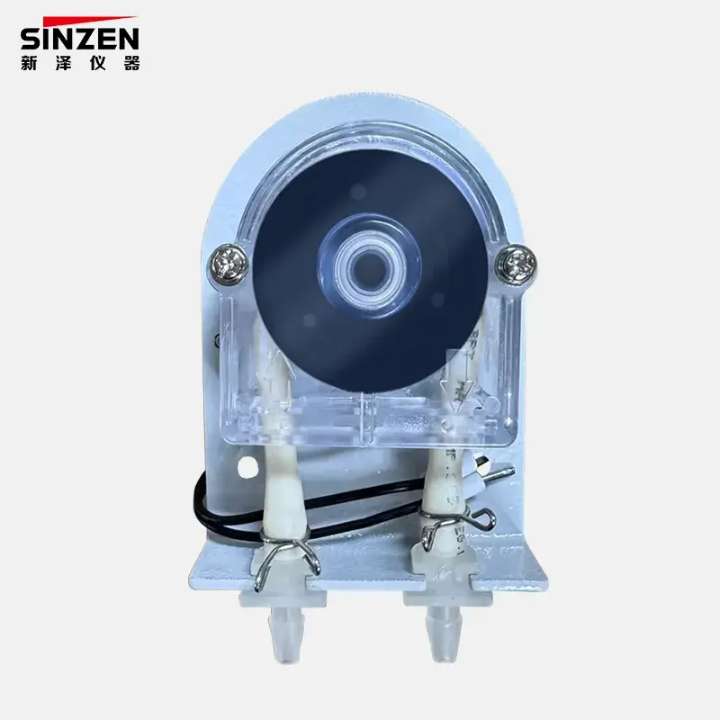
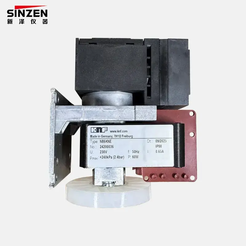
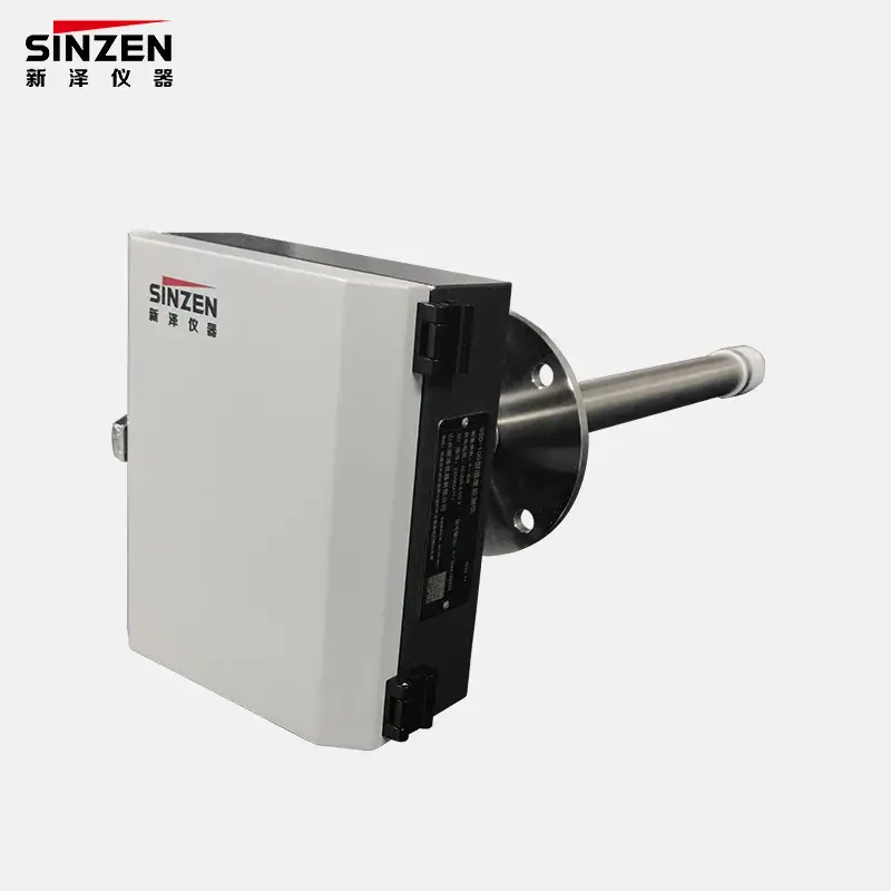
Direct answer:A humidity alarm can appear to fail after delivery because its power, wiring, relay logic, threshold, installation point, sample condition, or commissioning test differs from the ordered basis. First confirm what the device is intended to protect and whether it monitors ambient air or conditioned sample gas. In an ammonia leak alarm system, a humidity alarm is an auxiliary device; it does not detect ammonia or replace the gas detector.
Start by separating three different alarm functions
The words “gas alarm” can hide different measurement tasks. An ammonia leak alarm is selected to detect NH3. A chlorine leak alarm is selected to detect Cl2. A humidity alarm detects moisture or a humidity condition. These devices may appear in the same facility or cabinet, but they do not measure the same variable and are not interchangeable.
This boundary should be checked before troubleshooting. A buyer who expects a humidity alarm to respond directly to an ammonia release has a specification problem, not a defective humidity sensor. Where a humidity alarm is installed in a sample-conditioning train, its purpose may be to warn of moisture breakthrough or an unsuitable sample condition before gas-analysis equipment is affected. Its exact function depends on the system design.
A fixed toxic-gas detector, by contrast, is positioned and configured for the target gas and site hazard. The detector model, sensing principle, range, alarm setpoints, environmental limits, cross-sensitivity information, and installation method must be reviewed for the intended gas. A generic humidity device cannot provide that evidence.
Confirm the ordered duty before powering the device
Retrieve the purchase specification, approved datasheet, wiring diagram, and supplier quotation. Identify whether the unit was ordered for ambient humidity, sample-gas moisture, condensate protection, or a high-humidity interlock. Record the specified supply, output type, relay contacts, threshold, reset behavior, installation orientation, pressure condition, and connector or terminal arrangement.
If the purchase record only says “humidity alarm,” the acceptance basis is incomplete. The same label can cover devices with different sensing ranges, outputs, alarm logic, and environmental conditions. Before declaring a failure, ask the supplier to confirm the delivered model and compare its nameplate and configuration with the order.
The product category also matters. A standalone device listed among gas alarm devices may have a different installation role from a humidity monitor integrated into an analyzer panel. The system drawing should show the actual sensing point and the equipment affected by the alarm.
Check power and wiring without assuming the relay logic
Many apparent delivery failures begin with an electrical mismatch. Verify the rated supply against the actual supply before energizing the unit. Check polarity where applicable, terminal assignments, grounding, connector seating, cable continuity, and any fuse or protective device. Measure the supply at the alarm terminals under load rather than only at the cabinet power source.
Next identify the signal type. A dry-contact relay, analog output, and digital communication link require different tests. For relay outputs, confirm common, normally open, and normally closed terminals. “Alarm active” may close one contact or open a fail-safe circuit, depending on the agreed logic. A PLC input that is configured for the opposite state can make a healthy device appear permanently alarmed or permanently normal.
Ask whether loss of power should create a fault indication. If fail-safe behavior is required, define it in the cause-and-effect schedule and test it deliberately. Do not change wiring until the device diagram and plant logic have been reconciled.
Verify the sensing point and sample path
A humidity alarm only responds to the condition at its sensing element. If it is intended to detect moisture breakthrough in a conditioned sample, its location relative to the cooler, separator, filter, pump, and analyzer is critical. A sensor installed upstream of the relevant moisture-removal stage will see a different condition from one installed downstream.
Inspect the complete sample path for bypasses, closed valves, loose fittings, blocked tubing, reversed flow, dead legs, and leaks. Confirm that sample gas actually reaches the sensing chamber at the expected flow and pressure. If the system is under suction, an air leak can change the measured moisture condition. If the sensor is isolated by a valve or plugged fitting, a functional bench test may not represent the installed duty.
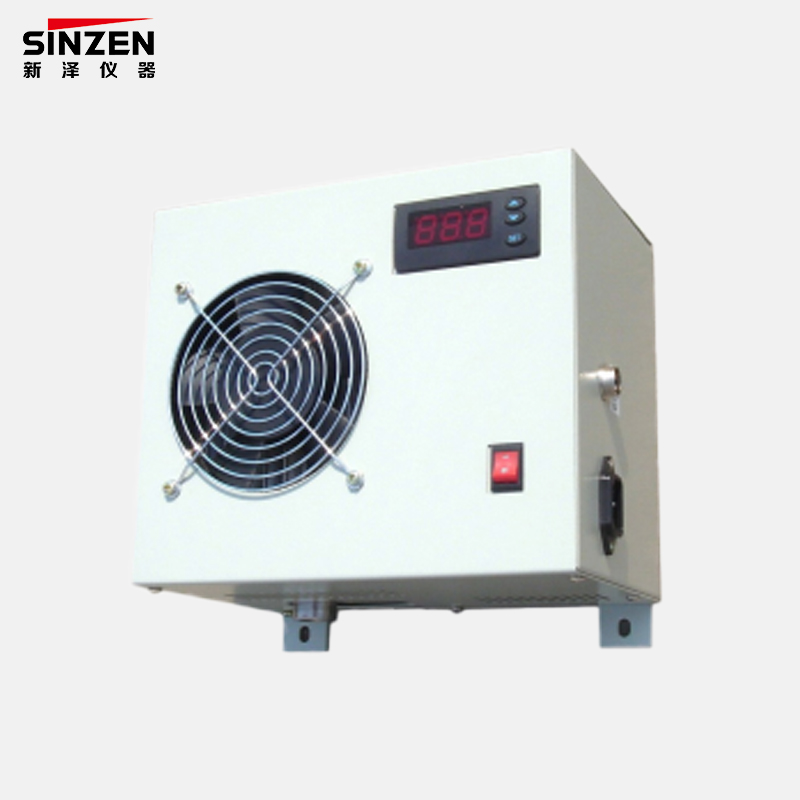
Where condensation control is part of the design, verify operation of the electronic condenser, drain, separator, and associated tubing. A humidity alarm cannot compensate for a cooler that is not powered, a drain that is blocked, or tubing routed so that condensate pools and later moves as a slug.
Distinguish high humidity from liquid water exposure
Humidity sensing and liquid-water tolerance are not the same. A sensor may be specified for a broad relative-humidity range yet still require non-condensing operation. If liquid condensate reaches the sensing element, the response may become saturated, slow, unstable, or temporarily biased. The correct action depends on the device instructions; uncontrolled heating, disassembly, or solvent cleaning can cause further damage.
Inspect transparent chambers and drains for visible droplets, but do not rely on appearance alone. Record sample temperature, pressure, ambient temperature, and the temperature of the sensor body and tubing. A temperature change can move the sample across its dew point even when the upstream process condition has not changed. Cold surfaces after transport or start-up may also create temporary condensation.
If a continuous moisture value is needed rather than a simple alarm, compare the required function with a humidity monitor for gas systems. The selection should follow the measurement range, sample condition, output, response expectation, and maintenance method—not the product name alone.
Review threshold, hysteresis, delay, and reset
A device can be electrically healthy but configured differently from the site expectation. Check the alarm threshold and unit, whether the threshold applies to relative humidity or another moisture variable, the hysteresis or deadband, any activation delay, latching behavior, and reset method. Compare the actual settings with the approved alarm schedule.
Thresholds should be linked to the equipment being protected and the normal sample condition. A setpoint copied from another project may cause nuisance alarms or fail to give useful warning. If the alarm protects an analyzer, ask the analyzer or system supplier to define the acceptable inlet condition and the required response when the limit is crossed.
Use a controlled test method to challenge the sensing point. The test should have a known or independently measured condition suitable for the device. Simply breathing on the sensor, applying wet tissue, or injecting uncontrolled steam does not establish accuracy and may expose the element to condensation.
Use the symptom to select the first check
| Observed symptom |
First checks |
Evidence to record |
| No power indication or output |
Supply rating, polarity, fuse, terminals, connector and load voltage |
Model, rated supply and measured terminal voltage |
| Alarm always active |
NO/NC logic, threshold, wet sensor, condensate, wrong sensing point |
Relay state, settings, sample and ambient conditions |
| Alarm never activates |
Sample flow, bypass, blocked line, threshold, output mapping |
Flow path, challenge method and PLC input state |
| Intermittent alarm |
Condensate slugs, loose wiring, temperature cycles, unstable flow |
Time-stamped conditions and event sequence |
| Slow recovery |
Liquid exposure, dead volume, contaminated chamber, reset logic |
Exposure history, recovery time and device instructions |
| PLC state disagrees with local state |
Contact selection, scaling, register mapping, fail-safe convention |
Terminal measurement and control-system logic |
Do not use humidity troubleshooting to approve a toxic-gas detector
Humidity can affect the operating environment of some gas sensors, but that does not make a humidity alarm a substitute for gas-specific qualification. For an ammonia leak alarm or chlorine leak alarm, buyers should separately review the target gas, range, sensing principle, response and recovery criteria, alarm levels, environmental limits, cross-sensitivity information, calibration gas, bump-test method, mounting position, outputs, certification requirements, and maintenance interval.
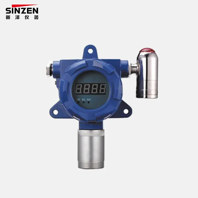
The relevant detector may fall within a toxic gas alarm detector selection. Ask the supplier for the exact model datasheet and verification procedure. Do not assume that performance information for NH3 applies to Cl2, or that a detector suitable for a clean indoor area is suitable for a wet, corrosive, dusty, or condensing location.
If the gas detector and humidity alarm participate in one shutdown or ventilation sequence, create a cause-and-effect table. It should show which device initiates each action, the alarm level, delay, latching rule, reset authority, fault behavior, and output destination. Test each input independently before testing the combined sequence.
Inspect transport, storage, and installation history
A unit that passed a supplier test can still arrive with a loose connector, damaged cable, contaminated chamber, or configuration change. Record the packaging condition, shock or moisture evidence, storage duration, storage environment, and the interval between unpacking and commissioning. Compare the received model, serial number, accessories, and documentation with the packing list.
Allow the device to reach the specified installation condition before testing, particularly after movement between cold and warm environments. Inspect seals, tubing caps, fittings, and sensing chambers without opening protected assemblies unnecessarily. Photograph the installed orientation and connections so the supplier can assess the setup remotely.
Installation changes should be controlled. If the cable length, power supply, sample tubing, cooler arrangement, or PLC logic differs from the factory test, record the deviation. Troubleshooting is faster when the supplier can see exactly what changed between shipment and site.
Run a staged commissioning and acceptance test
Commissioning should isolate variables. First verify the model and configuration. Second verify power and the local output. Third apply a controlled humidity condition appropriate to the device. Fourth confirm the relay, analog, or digital signal at the receiving controller. Fifth test the alarm action, reset, and loss-of-power behavior. Finally, run the device in the actual sample path and observe it through representative operating transitions.
Define pass criteria before the test. These may include the required state below and above the setpoint, allowable activation and recovery times, relay logic, displayed or transmitted value where applicable, and correct plant response. Use the manufacturer’s instructions and project specification for values; do not invent acceptance limits at site.
Information to send with a failure report
- Product model, serial number, purchase reference, and approved datasheet
- Supply rating and measured voltage at the device
- Wiring diagram, terminal measurements, and PLC or DCS logic
- Threshold, hysteresis, delay, latch, and reset settings
- Photos of installation, orientation, sample tubing, cooler, and drain
- Sample pressure, flow, temperature, humidity condition, and condensate observations
- Time-stamped symptom, challenge method, and actions already taken
A representative delivery investigation
Representative scenario — not a claimed customer case.
A panel humidity alarm shows a normal local state, but the control system displays a constant alarm after delivery. The device is initially suspected of being defective. A terminal check shows that the PLC input was wired to the normally closed contact while the control logic expected a normally open signal. The hardware is functioning, but the interface convention was never fixed in the purchase specification.
The buyer records the approved alarm philosophy, rewires only after authorization, and tests normal, alarm, reset, and power-loss states. The acceptance document is updated with the terminal numbers and fail-safe behavior. The correction addresses the root cause and prevents the same ambiguity on replacement units.
FAQ
Can a humidity alarm detect an ammonia leak?
No. It detects a humidity or moisture condition, not NH3 concentration. An ammonia leak requires a detector selected and verified for ammonia. A humidity alarm may support sample-conditioning protection or environmental monitoring, but it cannot replace an ammonia leak alarm.
Is a chlorine leak alarm the same as an ammonia leak alarm?
No. The target gases, sensor selection, range, cross-sensitivity, calibration or test method, and site conditions must be assessed separately. Buyers should request the exact detector model and its supporting datasheet for Cl2 or NH3 rather than accepting a generic toxic-gas description.
Why does the alarm stay active after the sample is dry?
Possible causes include liquid exposure, moisture trapped in the chamber or tubing, hysteresis, activation delay, latching logic, a high threshold setting error, or opposite relay interpretation. Record the conditions and follow the device recovery and reset instructions before deciding that the sensor has failed.
What is the first electrical test after delivery?
Confirm the delivered model and rated supply, then measure voltage at its terminals under load. Verify polarity, terminal assignments, relay common and NO/NC contacts, signal type, and receiving-system logic. Do not rely only on cabinet labels or wire colors.
Should buyers test a humidity alarm by applying water?
Not unless the manufacturer’s procedure specifically permits it. Liquid water may saturate or damage a sensor intended for non-condensing humidity. Use a controlled challenge condition and an independent reference suitable for the device’s measurement principle and range.
When should a buyer request replacement rather than reconfiguration?
Request the supplier’s assessment after the model, supply, wiring, settings, installation, sample condition, and test method have been documented. Replacement is appropriate when evidence shows the delivered unit is incorrect, damaged, outside its stated performance, or unable to meet the approved specification.
Send evidence before requesting a replacement
For faster technical review, send SINZEN the product model, serial number, order reference, approved duty, power and wiring data, alarm settings, sample conditions, installation photographs, symptom timeline, and controlled test results. Submit the package through the SINZEN contact page and state whether you need troubleshooting, replacement assessment, or a revised device selection.